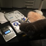
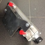
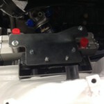
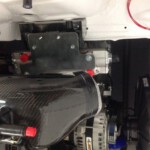
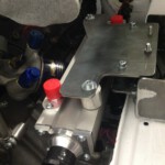
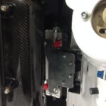
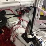
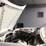
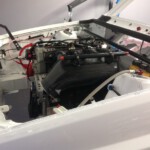
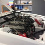
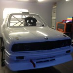
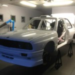
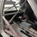
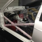
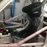
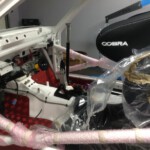
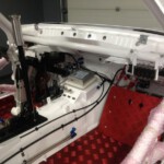
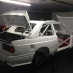
To be honoust there is also another (more important) reason. Being quite lazy, Dirk does not have the intention to make a move with his right foot to create a throttle blip on each downshift. For that reason we chose a drive by wire system. For once it was not home made but bought from DTA. We don’t have the time to invent this ourselves and it needs some serious testing. If the system does not work it might have nasty consequences and we don’t want to experience this.
The only thing we needed to alter were the sensors. We are still sticking to the good old P+G (Penny and Giles) sensors but we needed to add some signal conditioning to map the pedal sensor on the normally used Bosch sensors.
This could have been avoided by doing a custom calibration but this has an high NRE and we only need a few sensors. Therefore we decided to use a standard sensor and create a small print that will be added into the connector.
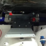
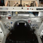
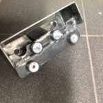
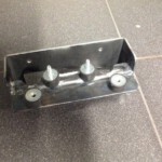
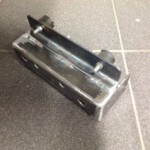
We are now developping a bracket for the actuator and an add-in for the Tilton peal box.
To be continued..
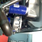
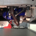
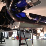
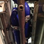
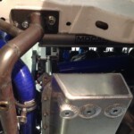
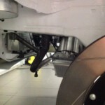
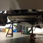
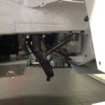
What we thought would be a walk in the park turned out a very long nightmare. The first problem we had was to find a suitable spot to install the heat exchanger.Underneath the radiator was possible but it was much too close to the crackshaft pulley. At any small incident the sensor could be hit so we abandonned that idea.
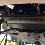
Because every decent rally car has a plate underneath the car to protect the crankcase we also wanted one !
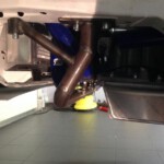
We mounted a big 25CrMo4 pipe between the two front chassis bars. During the build up of the car we already welded fixation points in the chassis bars so we now only needed to make a supporting plate to weld the pipe on.
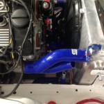
Coming up next ; we are going to place some brackets on that pipe to fix the silicon water tubes
October 2010, a few kindred spirits with an extreme passion for rally gathers to found R-Box.
A new Rally project is born.
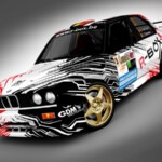
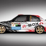
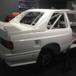
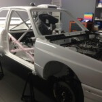
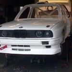
Almost 3,5 years and 1008 Pepsi Max’s later we proudly present the R-Box M3 car design.
This is one of the last milestones on our way to the finish (or is it a start) for the R-Box rally project.
It has been waiting on our to do list for some time list but nobody seemed to lose any sleep on it.
Because the temperature was high we opened the garage door and the spirit amongst the R-Box guys also rose ! It’s always a pleasure to breath fresh air (and drink cool beer/Pepsi Max) while working on the car…
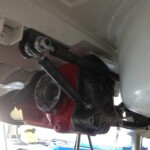
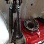
Since we didn’t want to lose a lot of time we went for a support we could finish ourselves without needing to outsource it (eg lazering, anodizing,…)
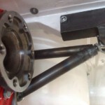
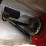
It turned out as a straightforward triangular construction in Cr25Mo4. Add some uniballs , a few bolts and nuts stirr and …ready !
It just needs to be powder coated !
Just a quick glance at the electrical department…
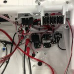
We did not succeed in building a “fuseless” car. We used a few traditional fuses for the front windshield heating, EPS … In all these cases we were not convinced that measuring the current had an added value so we just went for the good old fuses solution.
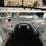
Because we are no fuses-fans we are trying to hide them as best as possible by putting them underneath the dashboard.
BTW : the first test with the windscreen wiper engine and the windscreen washer pump was a succes…We can proudly state : He’s or is it she’s alive !!
In every rally you can find BMW’s with broken, thorn apart or destroyed output shafts. We don’t want to be part of this club… Therefore we want to minimize the risks !
We are going to use reinforced shafts and polished heads but even more important is to determine the right length.
To help us find the correct length we transformed an old M5 output shaft (generously donated by ACG) to a measuring tool.
We are going to loose some sleep on it and will come back later with the correct lenght…
to be continued

