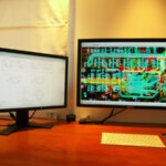
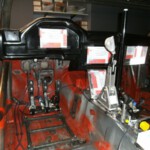
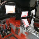
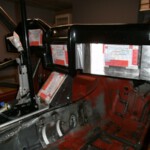
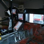
The display controllers are being produced by GDM Electronics and meanwhile we tried to find the right positions for the units. Eventually we use 4 simular controllers and the only difference between them is the PCB assembly. For each display an extended temp 7inch TFT panel with touchscreen is used.
Display 1 (pilot) is kept very minimalist since we think that our pilot has better things to do then looking at the display. It consists of a big grafic ev counter with the selected gear displayed in the centre
8 light guides that canalize the light of 8 RGB leds are positioned at the upper side of the panel.
These leds are used for the shiftlight and to highlight possible alarms.
In road mode the speed of the car is displayed to avoid traffic fines on the connection rides.
Display 2 (centre of the dashboard) displays all motordata, brake pressures and brake balance (front & rear). This data is collected by the CAN bus of the ECU. The information is divided into different tabs selectable via the touch. Default display is the water and oil temperature, fuel pressure, oil temperature from the gearbox and the diff,… When a parameter goes out of spec the corresponding tab is selected and the background turns red . It is also possible to program the RGB leds to highlight any failure !
Display 3 (navigator)
This is the most sophisticated of them all. Mainly trip/chrono with a lot of exra features.
A cell phone message box to communicate wih the team or the time keepers is situated at the bottom of the display. To get a real time overview of other competitors we are also developing a tablet app where the time guys at the FF put in the finish times that are forwarded to the navigator display. Even the complete rally iternary can be displayed and adapted at all times via the touch.
The timer function is activated by the navigator by means of a foot switch. The moment the wheels start turning the timer starts to run and the starting time is automatically sent to the team at the service.
Each SS is automatically divided into sections ( via GPS Data) and the navigator is able to compare the new times with previous passages or a calculated average. This way we can see whether we are going faster or slower and a predicted ETA is calculated. By looking at the remaining stage time we can decide if we are going to change a flat tyre or not.
At the FF the navigator operates the foot switch again and the SS time is sent to the crew.
One of the built in features automatically generates a text message providing GPS coordinates when the speed on a SS is lower the 5km/h during 30 seconds. Also motor date ( eg temperature) going out of spec is reported this way.
Display 4 is located just in front of the gear lever and is only used as an interface to switch users on and off. Custom buttons can be displayed and operated via the touch screen.
When a button is activated a CAN message is sent to the appropriate PWR box that converts the command into an action. ( eg switching on a light)
The PWR boxes are spread over the car and have 8 outlets of 20A each that can be coupled parallel.
The max current for each PWR box is limited to 100A to have normal connectors. The current from each channel is carefully measured and logged and when it goes out of the max range the current is limited to a fixed value. When the problem stays the power consumer is switched off. This way fuses are no longer needed.
The power supply checks are made in hardware and the control circuits of the MOSFETs is redundant and SEU protected.
The first units are expected late june. The dash still needs to be completed and flocked.
To be continued…

