As mentioned earlier, the intention is that we will develop all electronics ourselves. ECU, display controllers, power controllers, ignition/coil drivers,….
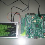
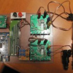
To reduce development costs, we try to test as many concepts as possible with evaluation kits and test platforms (sample boards).
The intention is to simulate as much as possible and write software on these test platforms so that we can hopefully use our protos without too many patches for real live testing in the car.
I first started with the display controller with the sole purpose of being able to write to the TFT which was done quite quickly. At the moment I am putting the finishing touches to the schedule and I can start working on the layout shortly. The TFT controller has 2 separate CAN buses, 1 is used to communicate with the ECU (forwarding all engine data) and the other CAN bus is used for the user interface (including capacitive touch keypad, pedal switch for chrono,…)
On the TFT controller there is also a GPS, GSM and wifi module so that on the one hand we can show all kinds of messages from the team immediately on our displays and on the other hand our position, intermediate times, motor alarms,… automatically sent to the team via SMS.
The Wi-Fi is used to communicate with a PC during service to transport collected data and/or make changes to the ECU’s set-up parameters. This is to avoid that someone stumbles over cables during the service or has to stand somewhere with a PC in the rain.
Furthermore, we have put 16 RGB LEDs at the top of the TFT that can be controlled independently in all colors for shiftlight, alarms,….
The backlight of the TFT is controlled by a light sensor that continuously measures the ambient light.
Board 1 is the TFT controller that we are going to make first because it can also be very useful to debug the rest.
Board 2 is the coil/ignition driver. The test platform has meanwhile undergone a very long endurance test at a simulated speed of 12000 rpm and has proven to be bulletproof. Without going into further details some features of our custom driver :
programmable H and L current (pe2ak and hold) that can switch modes in a few microseconds. It is a current mode control loop i.e. the set currents remain constant regardless of the battery voltage or the impedance of the coils. Undervoltage lock out below 5V. The driver can deliver 10A and is 100% short-circuit resistant. This board is also ready to go to layout.
Board 3 is going to be the ECU itself. Even though most of the features are fixed, a full update will be posted later. Like the TFT controller, the heart of the ECU is a Smartfusion cSoC (FPGA + Cortex M3 + Analog Computing Engine). In addition to managing the engine, the ECU will also control the actuator of the gearbox over a separate CAN bus.
Board 4 is going to be the sensor board. This unit will mainly measure temperatures (TCs, NTCs, PT100s) and pressures and convert them into CAN messages which are then sent to the ECU.
Board 5 will become an intelligent power switch box to switch and/or control all kinds of devices such as light, pumps, fans,… again about a CAN bus. As a result, we save a lot of wire and we do not need fuses at consumer level. All flows are continuously monitored and software thresholds can be set moderately to switch things off, generate alarms,… An additional advantage is that, for example, worn bearings of a pump can be detected early and can be replaced preventively before the part breaks down. All this data can also be sent to the team automatically during driving. For example, if the water temperature exceeds a preset soft alarm.
Further details and features will be posted later. We will probably also make an offline test set-up with all units, which will facilitate the development of the software. We will try to post videos of this later.
Also pay special attention to the photos on our mascot who assists us with advice and deeds when we no longer see it
to be continued…


